donderdag 21 maart 2019

Recovering data from a corrupted SD card with Linux

1.Introduction


So the other day, someone asked me to have a look at their SD card. It had thousands of images on it from their holiday trip, but the card somehow got corrupted. It did not even show up anymore in windows when plugging in.. I said I'd quickly try to plug it in linux, and see what happened.

Eventually I managed to get 30GB out of the 64GB back with the help of photorec and a kernel driver patch!

I thought I'd share some of my findings of how SD cards work and how I managed to do this recovery.

2.Some background reading on SD cards and corruption


(Feel free to skip this section and go directly to the Linux part. Couldn't resist given some background:)


2.1 SD card background


SD cards, just like SSDs, consist out of some form of NAND flash, and a "controller" chip to talk the SD protocol to a PC, and interface with the flash and to "maintain it". NAND flash is increasibly cheap to make, but   (especially MLC/TLC/..) has serious limitiations like that you can only write a single spot 1000 times and that you regularly have to reread sections to avoid them from going bad. The controller hence tries to be clever, and tries to use the NAND flash as optimally as possible.

How well it succeeds in doing this, typically depends on two things:
 - The quality of the controller (and its firmware)
 - How the card is being used (how much data is written to it)

Afbeeldingsresultaat voor sd card controller sandisk
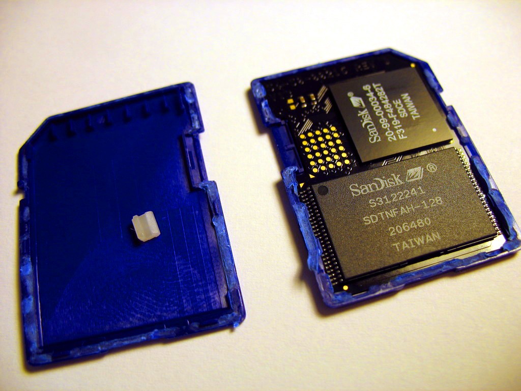
 (An example of someone who opened up the card. The NAND flash below and controller above are visible.)


SSDs actually support stuff like TRIM, to tell the controller which parts of the "virtual drive" are actually not used anymore, and hence can be used for the wear-leveling pool of the controller. SD cards typically don't have this feature; and hence once you write you card full once, wear-leveling is going to have to move a lot of data around very quickly, reducing the lifetime of your card very quickly.

Anyway, lots more to be said about this topic, but for this post, I'll focus a bit on what happens when stuff goes bad.

(If you are interested further in tearing down these things and getting to the bottom of them, I really also recommend checking out the post from bunniehttps://www.bunniestudios.com/blog/?p=3554https://youtu.be/r3GDPwIuRKI ) 


2.1.1 Corruption in SD cards and recovery scenarios


If the NAND flash starts failing (because it was written to too much by the controller (either because it was a stupid controller, or the controller had no choice due to usage)), the best case scenario is that the controller detects this. In fact, it typically will detect "bad blocks", which will become more and more common over time, and tries to avoid those sections in the future. If enough error correction was used, the data in the newly bad block might be recoverable, but otherwise the data is lost forever.

Controllers will typically try to avoid too much "damage" or dataloss on a card, by forcably putting the card in permanent read-only mode. Whatever data was lost will stay lost, but at more data writes (and wearleveling) are halted to prevent  further harm.

I have seriously had already 2 SD cards and 1 USB stick going permanent read-only like this.


If the card does not prevent corruption soon enough, and corruption occurs, there are a few places where it can happen:

- The "controller data" (which keeps track of which data is where in NAND (since data is moved around constantly for wearleveling purposes))
- Criticial filesystem data (e.g. for FAT, the FAT table)
- Actual data (if some JPEGs are stored, parts of them might be bad)

The second two cases are pretty much the same stuff as you could have on a regular magnetic drive. The classic recovery tools can help you out. You can still try to take a byte-per-byte backup first, and analyze data from there.

In the first case however is by far the worst. If the controller does not know which part of the NAND maps to what anymore, it might just give up altogether, and not even show up as an SD card anymore (e.g. not respond to SD card commands). Perhaps it will still respond for specific regions, or it might just show the regions as corrupt. All of this is guess work, and fully SD-card specific.

The typical "recovery" scenario in this case, is to actually physically open up the card, and extract or directly probe the NAND chip, to get the raw data out of it. What is corrupt will still be corrupt, but at least you will get all the bytes out of the chip that were still there. Also recovering a "linear" disk out of the data is not trivial, since you need the controller data  for that, which may be corrupt in the first place. Companies offer this kind of service, but it is not cheap, and still does not guarentee full data recovery obviously

 
An example of how the NAND flash in an SD card can be interfaced to directly (a commercial service offered by companies).


3. A linux recovery attempt


So, given how bad stuff might be, plugging the card into linux could show up a number of things:

- Either nothing would happen (meaning the controller would fully have given up)
- The controller would still communicate a bit, but fail to respond to certain commands  <====
- The controller would show the full drive, but its data might be a bit corrupt.

Turned out to the be second case: The SD card would not reply to commands to retrieve data from certain regions, but would reply for others. 

Since the MBR was still intact, linux correctly recognized the data partition. However, the FAT table was corrupt, and when trying to read raw data from the drive, the kernel would stall for long periods of time before even responding to a control+c / sigkill


Experimentally trying out different regions to start with, I managed to recover gigabytes of data at over 10MB/s, but eventually the transfer would always bump into a "bad" region and slow down to mere bytes per second.

Aside form the fact that it was super slow, there -was- data coming out of it. However, without a FAT, there was no way of knowing what was actually part of a file and what not. Photorec to the rescue!


3.1 Photorec to the rescue


Photorec (https://www.cgsecurity.org/wiki/PhotoRec - also an official debian package for example)  is an awesome piece of software. It simply ignores a filesystem, and tries to recover files based on their header signature. As you could have guessed, it certainly can recover pictures.


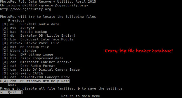
My very first run immediately turned up some pictures already! Also analyzing the few gigabytes of data that were quickly retrievable were quickly parsed using a loopback device: I first made a fast dd-copy in a region the SD card still dumped data quickly to a file, and then mounted it as virtual device for photorec to use:


This was already quite a good success (I managed to recover some 4GB this way), but by far the biggest part of the drive (the other 60GB) was littered with "slow sections". This was too much data to just ignore. However, the estimated time to go through the entire drive was more than 100 hours. 

I then turned my attention to the linux kernel. Trying to figure out -why- the kernel slowed down so hard, and seeing if I could not tweak some sort of timeout in the kernel to speed up the process


3.2 The linux kernel SD card reader driver


lsusb and lsmod quickly showed which driver I was using for the SD card reader: rtsx_usb_sdmmc

A quick inspection of the code showed that the driver supports dyndbg. Hence, we can simply enable some more verbose debugging in dmesg with the simple command:


# echo "module rtsx_usb_sdmmc +p" > /sys/kernel/debug/dynamic_debug/control

This showed output like:


 rtsx_usb_sdmmc rtsx_usb_sdmmc.0.auto: sdmmc_request
 rtsx_usb_sdmmc rtsx_usb_sdmmc.0.auto: sd_send_cmd_get_rsp: SD/MMC CMD 13, arg = 0xe6240000
 rtsx_usb_sdmmc rtsx_usb_sdmmc.0.auto: cmd->resp[0] = 0x00000900
 rtsx_usb_sdmmc rtsx_usb_sdmmc.0.auto: sdmmc_request
 rtsx_usb_sdmmc rtsx_usb_sdmmc.0.auto: sd_send_cmd_get_rsp: SD/MMC CMD 13, arg = 0xe6240000
 rtsx_usb_sdmmc rtsx_usb_sdmmc.0.auto: cmd->resp[0] = 0x00000900
 rtsx_usb_sdmmc rtsx_usb_sdmmc.0.auto: sdmmc_request
 rtsx_usb_sdmmc rtsx_usb_sdmmc.0.auto: sd_send_cmd_get_rsp: SD/MMC CMD 13, arg = 0xe6240000
 rtsx_usb_sdmmc rtsx_usb_sdmmc.0.auto: cmd->resp[0] = 0x00000900
 rtsx_usb_sdmmc rtsx_usb_sdmmc.0.auto: sdmmc_request
 rtsx_usb_sdmmc rtsx_usb_sdmmc.0.auto: sd_send_cmd_get_rsp: SD/MMC CMD 13, arg = 0xe6240000


By looking at the logging  timestamps, it could be seen how sometimes read commands could take longer than 10 seconds before going into timeout! Surely this could be done better.

After a bit of looking, I found the cause:


--- a/drivers/mmc/host/rtsx_usb_sdmmc.c

+++ b/drivers/mmc/host/rtsx_usb_sdmmc.c

@@ -530,7 +530,7 @@ static int sd_rw_multi(struct rtsx_usb_sdmmc *host, struct mmc_request *mrq)

                pipe = usb_sndbulkpipe(ucr->pusb_dev, EP_BULK_OUT);


        err = rtsx_usb_transfer_data(ucr, pipe, data->sg, data_len,

-                       data->sg_len,  NULL, 10000);

+                       data->sg_len,  NULL, 100);

        if (err) {

                dev_dbg(sdmmc_dev(host), "rtsx_usb_transfer_data error %d\n"

                                , err);


Apparently, the SD card protocol is -so- tolerant for slow controller replies (because of the the whole wear-leveling load they must bare), that the driver must take these huge delays into account. (It -might- just still reply).

As a result, this patch is not "correct" according to the SD card spec. But in my case, it managed to increase the read speed of the card dramatically! 

I quickly patched the module, and rebuilt it for the current kernel. A simple module reload (without even a reboot) fixed the slowdown issue.

After a few hours, I managed to let photorec parse the full 64GB of the card!

4. The end result


Thanks to photorec, and a small kernel driver patch I managed to recover about 30GB of pictures out of the 64GB on the card!

Given the fact that the card did not show up anymore in windows at all (probably because of the same timeout issue), this is a pretty good result for a software-only recovery!

As mentionned, doing a physical teardown of the card and reading the NAND directly might have recovered just a bit more. But for a non-invasive method, I don't think this is a bad result at all:)


Thanks again for linux and the open source community:)


donderdag 15 februari 2018

Linux portable wifi guitar amp on an orange pi zero

Introduction

The problem

I have an electric guitar laying around as well as a cheap vox amp.  The problem with this is:

- The amp I have now has limited effects
- To avoid making too much noise during practicing I would like to use my wireless headset 
   The vox amp I have obviously allows a jack out to a wired headset, but that gives me two cables to the amp!


I have been playing around with little linux devboards (like the raspberry pi) for quite a while, and figured it must be possible to do –some- sort of amp emulation onto it. So I head out for a little project.

The solution

And behold, a wifi-connected linux arm box in my pants, serving as portable amp + wireless transmitter


You can download the full SD card image for the hardware here.
Just flash it, and use the same hardware as I did, and it will work! (password root:guitar , wifipassword: guitarguitar)
Surf though your favorite webbrowser to http://172.24.1.1:8000 and control all your virtual amp settings!


In case you are interested in all the details of the project, continue scrolling:)


The build and how-to


Step 1: Getting the basic hardware and software up and running


The guitar


You obviously need an electric guitar. For the audio output, I have simple converter to 3.5mm to connect to my linux box.

The linux board


For the hardware I bumped into an article from cnx software (https://www.cnx-software.com/2017/07/30/how-to-setup-an-orange-pi-zero-diy-smart-speaker-with-google-assistant-sdk/) showing a nice case for the orange pi zero along with an expansion board for some more USB stuff. It is small, has a powerful processor, enough USB ports, onboard wifi, and is very cheap (18$). Sure, a raspberry 3 would have done the trick too for a bit more money, but I thought I’d give this one a try now.

This is a small overview from http://www.orangepi.org/orangepizero/ :


When shipped along with the expansionboard and  case, it looks like this:


 An extra sound card


Even though the expansion board has a jack out, it does not offer jack-in. That’s sort of required to get the guitar sound inside of the processor. 2$ (!) gets you this USB sound card which will do just fine :


My wireless headset


This I had already (A Logitech H600), and use it mostly for my laptop. I’m very happy with it. It interfaces towards linux as just another USB sound card. Any other wireless headset will do, as long as it has linux drivers for it.


A power bank


To avoid having to be connected to the grid for power, I just use a 2A power bank, like this:


Everything together:


Step 2: Running linux amp software


Jackd and guitarix


I did not know this until I started this project, but as it turns out some people already have been working hard at exactly what I was searching for. The main project is called guitarix, and it uses the low latency jackd as backend.

Please do check out their amazing work at guitarix.org
They basically aim at running the software on a desktop pc, and using their graphical interface:


Together with jackd (qjackctl screenshot above) you can quite quickly turn a PC with a basic sound card (e.g microphone in and headphones out) into a guitar amp with loads of effects!

I would really recommend trying this out. You just need to download a liveCD. I used the one they recommend (AV linux) http://www.bandshed.net/AVLinux.html; and tried it on my laptop. And it worked!

I also got it to work with my headset, however I did need to set a samplerate of 48000 (instead of 44100, since the audio driver from my headset did not support that rate)

Running it on the orange pi


So far so good, I had the setup running on a PC. Now I just had to do the same thing on a smaller pc. Simple right?

Operating system

Where raspberry pi’s have a debian based distro called raspbian, these “other arm boards”  also have a distro backing them called “armbian”. It’s pretty cool, and worth checking out at https://www.armbian.com/orange-pi-zero/

I just downloaded the “stable” version, flashed it on an SD card, and ran it. It works. Just connected to Ethernet, let DHCP do its job, and log in

ogin as: root
root@172.24.1.1's password:
  ___                               ____  _   _____
 / _ \ _ __ __ _ _ __   __ _  ___  |  _ \(_) |__  /___ _ __ ___
| | | | '__/ _` | '_ \ / _` |/ _ \ | |_) | |   / // _ \ '__/ _ \
| |_| | | | (_| | | | | (_| |  __/ |  __/| |  / /|  __/ | | (_) |
 \___/|_|  \__,_|_| |_|\__, |\___| |_|   |_| /____\___|_|  \___/
                       |___/

Welcome to ARMBIAN 5.35 user-built Ubuntu 16.04.3 LTS 4.14.8-rt9-sunxi
System load:   0.17 0.21 0.18   Up time:       11 min           Local users:   2
Memory usage:  23 % of 493MB    IP:            169.254.6.213 172.24.1.1
CPU temp:      56°C
Usage of /:    14% of 15G

Last login:


Armbian also comes with a handy tool called armbian-config, which does the hard work for you to set up the wifi chip as APmode:


Once that’s done, we can continue with installing jackd and guitarix


apt-get install jackd qjackctl guitarix

Trying Jackd

So, how do we run jackd? On the liveCD, I used qjackctl to configure it. However, the orange pi zero has no HDMI output, so running graphical applications is not trivial.

I installed Xming (https://sourceforge.net/projects/xming/ ). This very cool piece of software runs an X server on windows. (If you run linux natively, you can of course skip this step, since you are most likely already running an X server)


Once that’s done, you can just start an SSH session with X-forwarding. If you run linux natively, this is just doing ssh –X root@IPADDRESS. In my case, I set up putty on windows do to the trick.


Once qjackctl ran, I tried to simply loop the audio from the input (microphone) to my headset (stereo). By clicking connections, you can do this. Note again that I had to match the samplerate to 48000 to make it work.


If I did change the frame size lower (to reduce latency) I did run into quite a lot of issues of xruns and hang-ups of jackd, which I addressed in the following steps. But at least now already the basic concept worked!

Trying guitarix

With jackd running, I tried running guitarix.

Success!


Even though there is still a huge delay, you can now use all the effects of guitarix on the mini PC!!


Step 3: Running guitarix headless (without x server)


A headless read-only system


Even though the proof of concept worked, I still needed X-forwarding to run guitarix. The end goal is of course is to run the deamons without any screen attached, just a boot. Moreover, one way or another, SD cards will let you down eventually when you use them as a rw filesystem. But as long as you use them read-only, it just works. And you can unplug the  device at any point in time, without ever having to worry about filesystem corruption.


Making jackd and guitarix run in a read-only headless environment wasn’t exactly trivial. But some googling and hands-on testing got me there.

Headless jackd


Since the jackd installed by the debian package was built with dbus, it does not like starting without any X-related dbus stuff apparently. But, there is a simple hack around this:


export DBUS_SESSION_BUS_ADDRESS=unix:path=/run/dbus/system_bus_socket

/usr/bin/jackd -dalsa -r48000 -p256 -D -Chw:Device,0 -Phw:Headset,0  &

Jackd did not have any issue not being able to write to the filesystem, so read-only mode worked just fine.

Headless guitarix


Guitarix needs the bash home variable in order to try and find the config. If I try to run a script from rc.local for example, this is not set. Hence, the following is needed:


export HOME=/root

Guitarix also really does not like read-only filesystems. It tries to write some config every time it starts, and if it fails, it gives up. So basically what I quickly came up with, is to mount a tmpfs in the guitarix directory, which is rw. The changes will be lost, but that’s fine by me. I tarred the current config of guitarix which I found nice, and made sure it was restored each boot.


mount -t tmpfs none /root/.config/guitarix/
mount -t tmpfs none /var/lib/misc/
cp /root/guitarixconf.tar /root/.config/guitarix/
cd /root/.config/guitarix/
tar xf guitarixconf.tar
guitarix -i system:capture_1 -o system:playback_1  -o system:playback_2 -b E:1 -nogui &


 Controlling guitarix through wifi


I now had the system booting directly into a mode where the linux amp kicked in, but what if I wanted to change a setting? Like the gain, effects, etc.

Turns out guitarix has a JSON-API and a python webserver with a basic webinterface to do just that!

Just start the python program after starting guitarix, and navigate to the website. Ideal for surfing to on your smartphone to control the device!


cd /root/guitarix-webui/guitarix-webui-0.34.0/websockify/
python websocketproxy.py --web=../webui '*':8000 localhost:7000


To allow using a smartphone to connect wirelessly to the box, you can configure a wireless hotspot on the zero. The armbian has a nice tool (like rpi-config) that allows you to set this up. If you want to do it manually, just configure hostapd and dnsmasq appropriately, and let linux take care of the magic.


Step 4: Reducing latency with a realtime kernel

I basically did step 2 and 3 in about one evening. Getting the latency down took more than double of the time, but was also a pretty cool investigation.

As every line of the jackd or guitarix documentation says, you should run this on a real-time kernel. The armbian image I downloaded did not run this, hence the issues when trying to go to lower delays. So, up to recompiling a new kernel!


RT-linux patching

In contrast to the raspberry pi, the linux kernel support for the orange pi (sunxi) is rather shady. Especially if you want the video acceleration, you basically are forced to stay at an old 3.x kernel, which is again different from mainline

This is important, since in order to get real good real-time performance, you should use 1) a recent kernel, and 2) apply the RT patch (https://rt.wiki.kernel.org/index.php/Main_Page)

There is a topic on armbian which covered this: https://forum.armbian.com/topic/1885-rt-patches-for-sun8i-kernel/

People reported good results by trying a current mainline in the armbian build tool and applying the RT-patch. So I set out to do the same.

Building a new kernel

Turns out that building a kernel for armbian is pretty easy. Just follow https://docs.armbian.com/Developer-Guide_Build-Preparation/


git clone --depth 1 https://github.com/armbian/build
cd build
./compile.sh
You get a nice menu that allows you to select which kernel to build, allows you to change kernel options etc.
It does automatically apply a set of patches in the folder “userpatches”

Building a specific kernel with the RT patch

At the time of writing, the latest mainline kernel with an RT patch was 4.18.8-RT9

I downloaded the patch, and placed it into the appropriate directory:

ls userpatches/kernel/sunxi-next/
patch-4.14.8-rt9.patch

Then I did not immediately find a way to specify to the build tool to fetch a specific tag of the linux kernel (instead of default to the very latest) Doing a small patch was the fastest way I got it working. :


diff --git a/config/sources/sunxi_common.inc b/config/sources/sunxi_common.inc
index 4fc872f..aae8829 100644
--- a/config/sources/sunxi_common.inc
+++ b/config/sources/sunxi_common.inc
@@ -24,7 +24,8 @@ case $BRANCH in

        next)
        KERNELSOURCE=$MAINLINE_KERNEL_SOURCE
-       KERNELBRANCH='branch:linux-4.14.y'
+       #KERNELBRANCH='branch:linux-4.14.y'
+       KERNELBRANCH='tag:v4.14.8'
        KERNELDIR=$MAINLINE_KERNEL_DIR

        GOVERNOR=ondemand

(Note that I used the following tag of the armbian build repo: 9531d1bc7ecd0f468e29e402ba00cbc7b7dd683f)

After running another compile.sh, and enabling the correct options in the linux kernel menu (PREEMPT_RT_FULL), this gives a new uboot and new kernel debian packages.

These can just be uploaded and installed on the target. A new reboot and you are running a very fresh, very fast recent linux kernel!


Fixing fixed frequency for effective RT behavior


A good program to test the RT behavior is cyclic test. The output looks somewhat like this:


Linux orangepizero 4.14.8-rt9-sunxi #1 SMP PREEMPT RT Sat Jan 6 14:36:31 CET 2018 armv7l armv7l armv7l GNU/Linux
/root/rt-tests/cyclictest -p 80 -t5 –n
# /dev/cpu_dma_latency set to 0us
policy: fifo: loadavg: 0.85 0.49 0.22 4/168 3083

T: 0 ( 3079) P:80 I:1000 C:   3297 Min:      8 Act:   17 Avg:   16 Max:      66
T: 1 ( 3080) P:80 I:1500 C:   2198 Min:      8 Act:   24 Avg:   15 Max:      50
T: 2 ( 3081) P:80 I:2000 C:   1648 Min:      8 Act:   11 Avg:   16 Max:      60
T: 3 ( 3082) P:80 I:2500 C:   1318 Min:      8 Act:   12 Avg:   15 Max:      44
T: 4 ( 3083) P:80 I:3000 C:   1098 Min:      9 Act:   17 Avg:   18 Max:      57

You should make sure the maximum latency stays below 100 at least
.
In my first attempts with my newly compiled kernel, this hit 3000+ regularly! Meaning the RT patch clearly was not effective. Turned out a bit more work was needed

CPU Frequency Scaling Govenor

Apparently, to save power and dynamically adjust cpu frequency, the linux cpu governor regularly changed frequency, and this had a very bad effect on the RT behavior. When forcing the governor to performance mode or userspace mode, I suddenly got much better results!


echo userspace > /sys/devices/system/cpu/cpufreq/policy0/scaling_governor
echo 960000 > /sys/devices/system/cpu/cpufreq/policy0/scaling_min_freq
echo 960000 > /sys/devices/system/cpu/cpufreq/policy0/scaling_setspeed

Forcing fixed frequency

You’d think that that was the end of it, and so did I. Strangely enough, even when forcing the governor to a fixed frequency, the linux kernel –still- once in a while (like after a minute, depending on jackd realtime settings) shifted frequency, causing massive spikes in latency, and freaking out jackd. After investigating the kernel a bit further, it seems that it has some sort of protection that it will force to a lower operating point (OPP) regardless of the governor, to avoid any damage to the CPU whatsoever. Even though that sounds like a nice feature, the CPU can handle this load just fine, and this just messes up the real-time behavior.

The final fix that I needed to do to get consistently good RT performance, was to remove all other operation points from the device tree! You can simply decompile the devicetree and recompile it using the DTC tool like so:


dtc  -I dtb -O dts sun8i-h2-plus-orangepi-zero.dtb > sun8i-h2-plus-orangepi-zero.dts
dtc -I dts  -O dtb sun8i-h2-plus-orangepi-zero.dts > sun8i-h2-plus-orangepi-zero.dtb

Once in the dts format, you just locate the operating points, and only leave in the 960Mhz.

And success! Cyclic test keeps running forever without any spikes!


root@orangepizero:~# uname -a
Linux orangepizero 4.14.8-rt9-sunxi #1 SMP PREEMPT RT Sat Jan 6 14:36:31 CET 2018 armv7l armv7l armv7l GNU/Linux
/root/rt-tests/cyclictest -p 80 -t5 –n
# /dev/cpu_dma_latency set to 0us
policy: fifo: loadavg: 0.85 0.49 0.22 4/168 3083

T: 0 ( 3079) P:80 I:1000 C:   3297 Min:      8 Act:   17 Avg:   16 Max:      66
T: 1 ( 3080) P:80 I:1500 C:   2198 Min:      8 Act:   24 Avg:   15 Max:      50
T: 2 ( 3081) P:80 I:2000 C:   1648 Min:      8 Act:   11 Avg:   16 Max:      60
T: 3 ( 3082) P:80 I:2500 C:   1318 Min:      8 Act:   12 Avg:   15 Max:      44
T: 4 ( 3083) P:80 I:3000 C:   1098 Min:      9 Act:   17 Avg:   18 Max:      57

Important sidenote of fixed OPP

One important sidenote of using a fixed opp, is that in very heavy load, the cpu actually becomes so warm that the linux kernel (having no other option since we removed the other OPPs) decides to reboot the device! I only saw this ever happening when running a parallel compilation on all 4 cores though. When just using it with guitarix/webstuff, I never got it to crash so far:) You can also just lower the frequency or go save with a heatsink of course if you’d want to.

Patching jackd to deal with latency spikes


While investigating the RT issues with the linux kernel, I also noticed that jackd really got completely messed up when it received a bit latency spike. Instead of noting an XRUN and just recovering, it never did recover. I always then had to kill the process with the SIGKILL, and restart it. Even though that works, it is really slow and requires manual action. Surely there must be a better way?

And there is. Turns out there was a bug in the jackd alsa driver when coping with xruns

In the function alsa_driver_xrun_recovery, the linux driver is not told to again reset its buffers to a sane position upon overrun. As a result, after a recovery, immediately another overrun can occur. To fix this, I just had to trigger a recovery (snd_pcm_prepare) after an actual xrun was detected:


if (snd_pcm_status_get_state(status) == SND_PCM_STATE_XRUN && driver->process_count > XRUN_REPORT_DELAY) {
       struct timeval now, diff, tstamp;
       driver->xrun_count++;
       snd_pcm_status_get_tstamp(status,&now);
       snd_pcm_status_get_trigger_tstamp(status, &tstamp);
       timersub(&now, &tstamp, &diff);
       *delayed_usecs = diff.tv_sec * 1000000.0 + diff.tv_usec;
       jack_log("**** alsa_pcm: xrun of at least %.3f msecs",*delayed_usecs / 1000.0);
       if (driver->capture_handle) {
           if ((res = snd_pcm_prepare(driver->capture_handle)) < 0) {
               jack_error("error preparing after xrun: %s", snd_strerror(res));
           }
       } else {
           if ((res = snd_pcm_prepare(driver->playback_handle)) < 0) {
                   jack_error("error preparing after xrun: %s", snd_strerror(res));
           }


I downloaded the source using apt-get source, and built it again with debuild –us –uc, and installed it locally. And voila, a working system!


Conclusion


This was a cool project, which hadn't been possible for the awesome open source community that provided many of the tools and toys to make this possible. 

Linux rocks:)


donderdag 22 augustus 2013

My Electric Scooter Project


The concept

The concept of my project, was to upgrade my (2 kW 48V) electric scooter (a Qwic Emoto 87), with an LCD display, showing the voltage of the batterypack, the current flowing through it, the current power usage etc.

From an electronics point of view, this is quite easy; Hook up the voltages to a resistor divider, measure the current via a shunt or something, and process this info using a microcontroller, which also controls the LCD.

The final result speaks for itself in the video's below:

(The finished project)


(The nutty testdrives)


In the next sections, I'll try to go over what I did exactly to get to this point. I'll explain what stuff I bought, how I put it together, how the software is designed etc. Hopefully I can inspire other folks with this info, and give something back to the online community, that has helped me get this far.

The Hardware


1. The Scooter

(I already had this part:). I own a Qwic Emoto 87 since 2011, and most likely lost the warranty already anyway:) Since everything about it is electric, hooking some nice electronics to it is not too hard!

2. The Microcontroller


 The microcontroller was by far the most fun of the project for me:) I never actually played a lot with Arduino's or anything before, so you can imagine the world that opened when I ordered by TI Stellaris Launchpad Evaluation board (for the amazing price of less than 10 euro's, including shipping!)

The board provides lots of GPIO pins that can be used for ADC measurements (for voltage & current in my case), and digital out (for the LCD).

There's quite some material online to get started (although not much compared to the arduino projects:). It's typically programmed in C, although there is even a project called Energia that allows you to use arduino-like code. But if you are a bit experienced in C, TI have an awesome free, open, very well documented library called stellarisware, that'll definitely speed up any development!
For more info on how I wrote the software etc, see the software section below

3. The LCD

For the LCD that would eventually go onto the dashboard, I first scowered the web to see if anybody had already connected an LCD to the launchpad before. Turns out the HD44780 had been connected before by "The_YongGrand", and he published the library online. Then I just ordered one off ebay for some 7 euro's.

4. The current measurement tool

 You might think a simple shunt would cut it. It would, but keep in mind that the scooter actually can draw some 40 amps at peak power, so choosing the shunt is not so trivial. You can try to find a one with a really small resistance value to avoid losing energy in it, but that pushes up the cost a bit. Thanks to a hint of somebody, I found these babies (see picture). They're precalibrated hall sensors, with the current flowing right through the chip on the lead-frame. In my case, I chose an "ACS756" chip, and ordered it off ebay again, for 6 euros


5. DC-DC converter

The LCD and microcontroller don't like 12V that much (let alone 48). A resistor divider can do the trick too, but is not very efficient and does not provide a stable output current*. A DC-DC converter efficiently gives you a stable output. You  can build one yourself using the LM , coil & caps, but I chose to be lazy, and ordered one off ebay again for 10 euros:) It takes in up to 30V.


* In retrospect, a voltage divider -might- have worked too: The backlight of the LCD is not very intolerant of fluctuations, and the microcontroller has a voltage stabilizer on board. In addition, the whole system only draws 0.3W. The battery pack is supposed to be a giant cap so voltage peaks shouldn't be too much of a problem. So if you want to save a few euro's, but risk resetting the microcontroller if the pack is going empty, you might as well try the resistor divider.

6. Electronics kit

If you're into electronics a bit, you'll probably have this stuff. But just to go over the shortlist of the things I used (that I can come up with):

- Breadboard
- Breadboard cables
- Pinheaders
- Soldering iron
- Multimeter
- Heat-shrink tubing
- A perfboard / stripboard (a prototype PCB)
- Gluegun (very useful, < 10euro's) :)
...

You can get most of this stuff quite cheap online/in your local hardware store

7. Mechanics kit

If you're opening the scooter, you'll need some screwdrivers and wrenches..


The software

On the TI website you can find sort of all the things you need, although other websites have better tutorials about how to get started in my opinion:) TI does have the 8 video's or so of the entire system, but I never bothered to see them because they took too long:)

(I did actually watch (/scrolled through) these video's: 
http://www.youtube.com/playlist?list=PLPW8O6W-1chwyTzI3BHwBLbGQoPFxPAPM
They're a very basic course for embedded programming, but they also show how to program the launchpad.)

Anyway, to get started, you'll first need an IDE.

The IDE: Code Composer Studio

I tried two IDE's, the IAR embedded workbench, and Code Composer Studio. The last one is developed by TI itself, and is a fork of Eclipse. I started with IAR, but landed at CCS:) I'm only going to cover using CCS here. (You can download it for free from TI's website, if you keep your code size limited)


(What Code Composer Studio looks like on my PC)

The Stellarisware drivers

To use the awesome library that is stellarisware, you'll first have to download & compile it. Later, you'll need to "link" the built library with all your projects, so that you can call code from it. I won't go into details, but just give a few pointers, regarding the project settings:

1) Make sure you include stellarisware, and any other libs you refer to


2) Predefined symbols: To correctly use/compile stellarisware, you'll have to specify your type of board


3) Linker search path:


The LCD Library

Turns out the HD44780 had been connected before by "The_YongGrand", and he published the library online. The lib & example are quite straightforward.

Also the adafruit site is very very helpful: http://learn.adafruit.com/drive-a-16x2-lcd-directly-with-a-raspberry-pi/wiring

Note that to get stuff from integers to strings, you'll need stuff from the C standard library. For simple microcontrollers, this is a bit overkill. However, TI has usnprintf functions in the stellarisware library that do the job just fine.

Using the temperature sensor with the ADC

Something quite irrelevant for this project, but wanted to refer to this guy anyway:)

Nemetila posted his/her code on ti's fora: http://forum.stellarisiti.com/topic/471-using-stellaris-launchpad-as-a-thermometer/
It shows how to do an ADC measurement, but also has a nice userspace application attached to the post! If you have the stellaris launchpad, this is definitely worth a go!

The Final Code

You can find the whole code on github:


The Assembly

Getting the whole system working on my desk was one thing. But getting it actually installed in the scooter proved to be a challenge on its own:) I spent more time on it that I anticipated, mainly because I underestimated the time it takes to open a scooter, solder 50 cables and a PCB, and getting everything back together nicely:)

The Breadboard Prototype


In practice, you don't write the entire software the first time, and then start prototyping. To the right, you can see a pic of me getting the LCD to work for the first time, using the library as explained above.

I can tell you, finally getting them letters on that screen is a good feeling:)


Once I got the LCD working, doing the voltage ADC measurements is quite trivial too. Testing the current sensor was more difficult, as I didn't have any current source of several amps.


I eventually just used the scooter's battery charger, and hooked up the sensor in series, together with a multimeter for calibration. Not extremely professional, but that did the trick.


The Scooter Battery Connections

1. Opening the Scooter

Just hooking up a few cables to the batteries might not seem a big a deal.  It did however take me a whole afternoon to get it done:)

Here's what the scooter looks like when you open it:

 The thing on the top-right pic is the 40A controller. As you can see, after 2 years of service, the scooter get preeeetty dusty inside!


2. Soldering the Hall Sensor


And here you've got some pics on the hall-sensor,
 with the battery connections soldered onto them. (The cables are actually way to thick, oh well:)


3. Connecting some cables to the batteries


 In the top-right picture, you can see quite well the spot where I put all the cable endpoints. There's a small "box" where a relais is located for the scooter's park-mode. Luckily, the box is too big for the relais alone, and can easily fit the TI launchpad and some other parts.

In this step, I just put all the cables there (making sure they didn't short-circuit!)


Later, I removed the isolation from the cables again (carefully making sure nothing short-circuited, as you can see in the picture to the right), to solder them to flat cable. (To connect to the prototype PCB).


4. Choosing a cable connected to the scooter ignition key as a power source

This came as an afterthought, but if you connect the DC-DC converter to the 12V (or 24) directly, it'll be on, all the time. Not a big deal (hardly uses power), except that it the LCD really starts to draw attention in the middle of the night. A simple fix is attaching the V+ not directly to the battery, but to a circuit connected to the ignition key.

Turn's out that in that little box I was working, that cable was present:) Took me a bit of reverse-engineering, but this is what the 4 cables of the relais are connected to:


If you press the (hydraulic) brake, the brakelight goes on, but also your accelerator doesn't work anymore.
If you press the "park" button, the relais fires, and the brake light goes on all the time (and the accelerator doesn't work anymore)

After a few measurements, the schematic above is what I came up with.
(I wanted to know all connections, because I also use the ground pin from there. I needed to make sure everything still worked in 'park-mode')


The Prototype PCB

Fitting the breadboard prototype into the scooter was a bit unpractical.

For one, it was just too big to fit into what seemed to the ideal place for the electronics. Secondly, you loose a good breadboard. Third, it's not exactly the most "sturdy" construction.


Hence, thanks to a hint, I went for the prototype PCB. (A PCB filled with metalized holes, in which you can fit components, wires, pinheaders, etc..)

On the left, you can check out the result. (Which really took quite a bit of soldering!)


Note that I just glued the DC-DC converter onto it:)
You can also make out the resistor dividers from the picture.

Note the pinheaders. Instead of just soldering the cables of the battery directly onto the PCB, I first soldered them to a flat-cable. On the PCB, you then just solder some pinheaders. Same for the cables that go to the LCD. Finally for the TI Launchpad, if you put the pinheaders at the correct spot, it just clicks into place:)

(Note that I actually wrongly 2strips of pinheaders, but was too lazy to remove them:) The one left-up is for the LCD, left down for the Scooter-Battery, right-up & down for the TI launchpad, and right-middle = not connected)


The picture on the right actually shows quite well how the system works. You can see the LCD & the connected flat cable, the Launchpad (connected via USB to my PC), and the prototype PCB.
(The flat-cable connection to the batteries is not attached here)

(The breadboard is just on the desk, but is not connected anymore)


When testing the prototype PCB at 12+V with the LCD or launchpad attached, things tend to blow up if you get it wrong..
Hint:  Try to design the PCB so that you clearly separate high-voltage connections from low-voltage connections.
If you clearly separate the high-voltage pins from the rest, you can spend extra attention when handling them, making errors less likely

If you short-circuit any 3.3V pin, most likely not much will happen. The LCD uses 5V, but most of the pins of the launchpad are even 5V tolerant. This means that if you by accident short-circuit any of those cables, you're probably fine. However, make contact between a 12V pin anything else, and things start to burn.


Putting it together

By far the most fun part, and the most stressy too! If you get it wrong, you blow up stuff, and you're set back again at least a few hours. Thankfully, aside from 1 microcontroller, I didn't loose too much:)


Attaching the PCB to the LCD & scooter.


Hooking up the TI Launchpad


Hooking up the LCD to the dashboard for a testdrive


Doing the first testdrive:)


And some basic tests:


Finally I mounted the LCD onto the dashboard (which took a bit of work too) :


And finally with a bit of tape to cover up the LCD (+ some glue to keep it waterproof), you get the final result: