The concept
The concept of my project, was to upgrade my (2 kW 48V) electric scooter (a Qwic Emoto 87), with an LCD display, showing the voltage of the batterypack, the current flowing through it, the current power usage etc.
From an electronics point of view, this is quite easy; Hook up the voltages to a resistor divider, measure the current via a shunt or something, and process this info using a microcontroller, which also controls the LCD.
The final result speaks for itself in the video's below:
(The finished project)
(The nutty testdrives)
In the next sections, I'll try to go over what I did exactly to get to this point. I'll explain what stuff I bought, how I put it together, how the software is designed etc. Hopefully I can inspire other folks with this info, and give something back to the online community, that has helped me get this far.
The Hardware
 1. The Scooter
(I already had this part:). I own a Qwic Emoto 87 since 2011, and most likely lost the warranty already anyway:) Since everything about it is electric, hooking some nice electronics to it is not too hard!
2. The Microcontroller
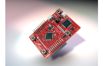
The microcontroller was by far the most fun of the project for me:) I never actually played a lot with Arduino's or anything before, so you can imagine the world that opened when I ordered by TI Stellaris Launchpad Evaluation board (for the amazing price of less than 10 euro's, including shipping!)
The board provides lots of GPIO pins that can be used for ADC measurements (for voltage & current in my case), and digital out (for the LCD).
There's quite some material online to get started (although not much compared to the arduino projects:). It's typically programmed in C, although there is even a project called Energia that allows you to use arduino-like code. But if you are a bit experienced in C, TI have an awesome free, open, very well documented library called stellarisware, that'll definitely speed up any development!
For more info on how I wrote the software etc, see the software section below
3. The LCD
 For the LCD that would eventually go onto the dashboard, I first scowered the web to see if anybody had already connected an LCD to the launchpad before. Turns out the HD44780 had been connected before by "The_YongGrand", and he published the library online. Then I just ordered one off ebay for some 7 euro's.
4. The current measurement tool

5. DC-DC converter

* In retrospect, a voltage divider -might- have worked too: The backlight of the LCD is not very intolerant of fluctuations, and the microcontroller has a voltage stabilizer on board. In addition, the whole system only draws 0.3W. The battery pack is supposed to be a giant cap so voltage peaks shouldn't be too much of a problem. So if you want to save a few euro's, but risk resetting the microcontroller if the pack is going empty, you might as well try the resistor divider.
6. Electronics kit
If you're into electronics a bit, you'll probably have this stuff. But just to go over the shortlist of the things I used (that I can come up with):
- Breadboard
- Breadboard cables
- Pinheaders
- Soldering iron
- Multimeter
- Heat-shrink tubing
- A perfboard / stripboard (a prototype PCB)
- Gluegun (very useful, < 10euro's) :)
...
You can get most of this stuff quite cheap online/in your local hardware store
7. Mechanics kit
If you're opening the scooter, you'll need some screwdrivers and wrenches..
The software
On the TI website you can find sort of all the things you need, although other websites have better tutorials about how to get started in my opinion:) TI does have the 8 video's or so of the entire system, but I never bothered to see them because they took too long:)
(I did actually watch (/scrolled through) these video's:
http://www.youtube.com/playlist?list=PLPW8O6W-1chwyTzI3BHwBLbGQoPFxPAPM
They're a very basic course for embedded programming, but they also show how to program the launchpad.)
Anyway, to get started, you'll first need an IDE.
The IDE: Code Composer Studio
I tried two IDE's, the IAR embedded workbench, and Code Composer Studio. The last one is developed by TI itself, and is a fork of Eclipse. I started with IAR, but landed at CCS:) I'm only going to cover using CCS here. (You can download it for free from TI's website, if you keep your code size limited)

(What Code Composer Studio looks like on my PC)
The Stellarisware drivers
To use the awesome library that is stellarisware, you'll first have to download & compile it. Later, you'll need to "link" the built library with all your projects, so that you can call code from it. I won't go into details, but just give a few pointers, regarding the project settings:
1) Make sure you include stellarisware, and any other libs you refer to

2) Predefined symbols: To correctly use/compile stellarisware, you'll have to specify your type of board

3) Linker search path:

The LCD Library
Turns out the HD44780 had been connected before by "The_YongGrand", and he published the library online. The lib & example are quite straightforward.
Also the adafruit site is very very helpful: http://learn.adafruit.com/drive-a-16x2-lcd-directly-with-a-raspberry-pi/wiring
Note that to get stuff from integers to strings, you'll need stuff from the C standard library. For simple microcontrollers, this is a bit overkill. However, TI has usnprintf functions in the stellarisware library that do the job just fine.
Using the temperature sensor with the ADC
Something quite irrelevant for this project, but wanted to refer to this guy anyway:)
Nemetila posted his/her code on ti's fora: http://forum.stellarisiti.com/topic/471-using-stellaris-launchpad-as-a-thermometer/
It shows how to do an ADC measurement, but also has a nice userspace application attached to the post! If you have the stellaris launchpad, this is definitely worth a go!
The Final Code
You can find the whole code on github:
The Assembly
Getting the whole system working on my desk was one thing. But getting it actually installed in the scooter proved to be a challenge on its own:) I spent more time on it that I anticipated, mainly because I underestimated the time it takes to open a scooter, solder 50 cables and a PCB, and getting everything back together nicely:)
The Breadboard Prototype

I can tell you, finally getting them letters on that screen is a good feeling:)

Once I got the LCD working, doing the voltage ADC measurements is quite trivial too. Testing the current sensor was more difficult, as I didn't have any current source of several amps.

I eventually just used the scooter's battery charger, and hooked up the sensor in series, together with a multimeter for calibration. Not extremely professional, but that did the trick.
The Scooter Battery Connections
1. Opening the Scooter
Just hooking up a few cables to the batteries might not seem a big a deal. It did however take me a whole afternoon to get it done:)
Here's what the scooter looks like when you open it:


2. Soldering the Hall Sensor


And here you've got some pics on the hall-sensor,
with the battery connections soldered onto them. (The cables are actually way to thick, oh well:)
3. Connecting some cables to the batteries


 In the top-right picture, you can see quite well the spot where I put all the cable endpoints. There's a small "box" where a relais is located for the scooter's park-mode. Luckily, the box is too big for the relais alone, and can easily fit the TI launchpad and some other parts.
In this step, I just put all the cables there (making sure they didn't short-circuit!)

Later, I removed the isolation from the cables again (carefully making sure nothing short-circuited, as you can see in the picture to the right), to solder them to flat cable. (To connect to the prototype PCB).
4. Choosing a cable connected to the scooter ignition key as a power source
This came as an afterthought, but if you connect the DC-DC converter to the 12V (or 24) directly, it'll be on, all the time. Not a big deal (hardly uses power), except that it the LCD really starts to draw attention in the middle of the night. A simple fix is attaching the V+ not directly to the battery, but to a circuit connected to the ignition key.
Turn's out that in that little box I was working, that cable was present:) Took me a bit of reverse-engineering, but this is what the 4 cables of the relais are connected to:
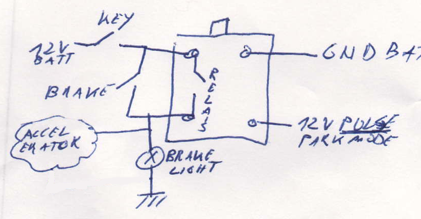
If you press the (hydraulic) brake, the brakelight goes on, but also your accelerator doesn't work anymore.
If you press the "park" button, the relais fires, and the brake light goes on all the time (and the accelerator doesn't work anymore)
After a few measurements, the schematic above is what I came up with.
(I wanted to know all connections, because I also use the ground pin from there. I needed to make sure everything still worked in 'park-mode')
The Prototype PCB
Fitting the breadboard prototype into the scooter was a bit unpractical.
For one, it was just too big to fit into what seemed to the ideal place for the electronics. Secondly, you loose a good breadboard. Third, it's not exactly the most "sturdy" construction.

On the left, you can check out the result. (Which really took quite a bit of soldering!)

Note that I just glued the DC-DC converter onto it:)
You can also make out the resistor dividers from the picture.
Note the pinheaders. Instead of just soldering the cables of the battery directly onto the PCB, I first soldered them to a flat-cable. On the PCB, you then just solder some pinheaders. Same for the cables that go to the LCD. Finally for the TI Launchpad, if you put the pinheaders at the correct spot, it just clicks into place:)
(Note that I actually wrongly 2strips of pinheaders, but was too lazy to remove them:) The one left-up is for the LCD, left down for the Scooter-Battery, right-up & down for the TI launchpad, and right-middle = not connected)

The picture on the right actually shows quite well how the system works. You can see the LCD & the connected flat cable, the Launchpad (connected via USB to my PC), and the prototype PCB.
(The flat-cable connection to the batteries is not attached here)
(The breadboard is just on the desk, but is not connected anymore)
When testing the prototype PCB at 12+V with the LCD or launchpad attached, things tend to blow up if you get it wrong..
Hint: Try to design the PCB so that you clearly separate high-voltage connections from low-voltage connections.
If you clearly separate the high-voltage pins from the rest, you can spend extra attention when handling them, making errors less likely
If you short-circuit any 3.3V pin, most likely not much will happen. The LCD uses 5V, but most of the pins of the launchpad are even 5V tolerant. This means that if you by accident short-circuit any of those cables, you're probably fine. However, make contact between a 12V pin anything else, and things start to burn.
Putting it together
By far the most fun part, and the most stressy too! If you get it wrong, you blow up stuff, and you're set back again at least a few hours. Thankfully, aside from 1 microcontroller, I didn't loose too much:)

Attaching the PCB to the LCD & scooter.

Hooking up the TI Launchpad

Hooking up the LCD to the dashboard for a testdrive
Doing the first testdrive:)
And some basic tests:
Finally I mounted the LCD onto the dashboard (which took a bit of work too) :


And finally with a bit of tape to cover up the LCD (+ some glue to keep it waterproof), you get the final result: